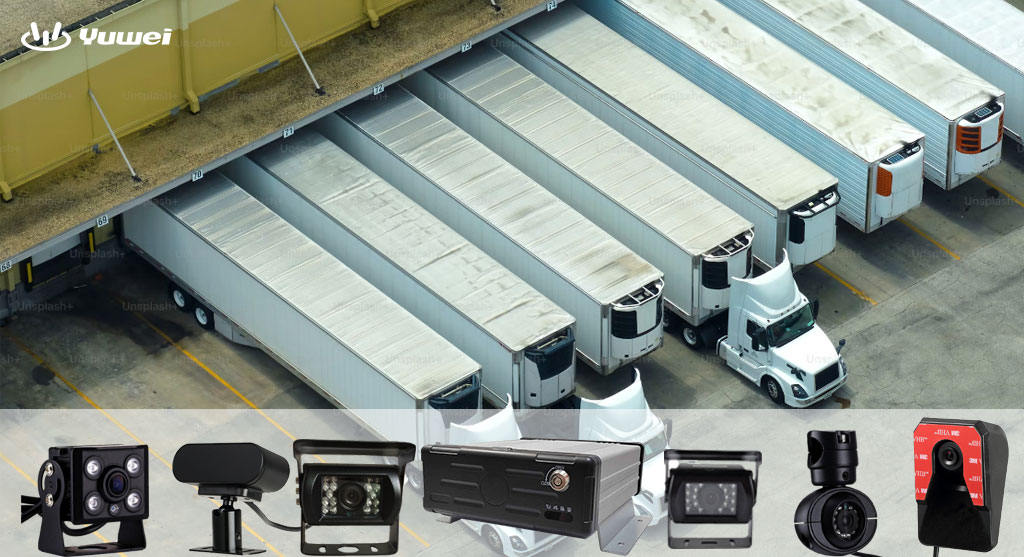


Heavy Truck ADAS System
Heavy Truck ADAS Systems
Introduction:
With the rapid development of automotive intelligence, ADAS (Advanced Driver Assistance Systems) are gradually being applied to heavy-duty trucks. The currently achievable functions include Lane Departure Warning (LDW), Forward Collision Warning (FCW), Automatic Emergency Braking (AEB), and Adaptive Cruise Control (ACC).

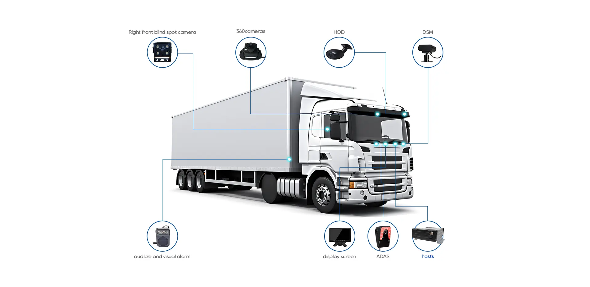
ADAS System Components
The ADAS system comprises three parts: sensors (input signals), controllers, and actuators (output signals). The sensors include front-mounted monocular cameras and millimeter-wave radars, while the actuators include the engine and EBS (Electronic Braking System).
hnweb_
ADAS System Circuit
There is a dedicated CAN line for communication between the radar and the camera to achieve data fusion. The controller built into the camera communicates with the EBS, engine ECU, BCU, and other electronic control units via PCAN.
1. Millimeter-Wave Radar:
The front-mounted millimeter-wave radar of the ADAS system is installed inside the front bumper of the vehicle. Since millimeter waves are reflected by metals, the radar can calculate the distance and relative speed of the target vehicle in front based on the time the waves are reflected back. The radar excels in measuring longitudinal distances. National standards require the radar to have an effective detection range of at least 150 meters.
2. Monocular Camera:
The camera, installed at the lower inner part of the windshield, is used to identify lane lines, vehicles, and pedestrian targets. The camera is advantageous in detecting lateral angles and positional relationships. The system uses camera signals to implement lane departure warning functions, while FCW, AEB, and ACC functions require the fusion of radar and camera signals.
ADAS System Functions
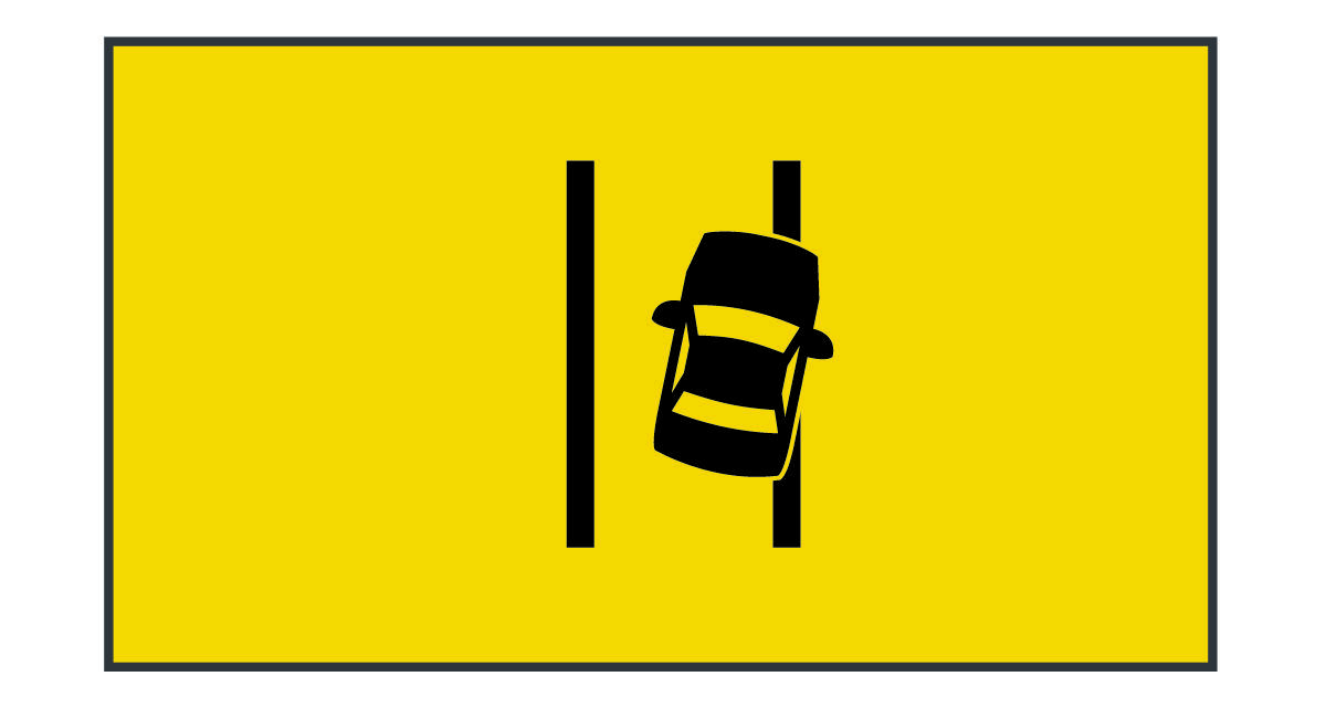
2.1 Lane Departure Warning Function:
Lane lines that meet national standards (solid or dashed white or yellow lines) can be identified, and when the vehicle speed is between 60-110 km/h, an unintended lane departure will trigger a lane departure alarm (the instrument alarm light flashes and the buzzer sounds). The LDW system also has requirements for lane conditions. It does not operate on sharp curves (turning radius less than 250m) or narrow roads (lane width less than 2.5m).
If the vehicle departs from its lane but the driver is actively controlling the vehicle (such as using the turn signal, making sharp turns, braking, or engaging the handbrake), the system will not issue an alarm.
2.2 Automatic Emergency Braking:
The system determines the most relevant target to the vehicle (i.e., the vehicle in front traveling in the same direction and closest in distance) through data fusion, ignoring vehicles in adjacent lanes. The AEBS system operates at speeds between 15-110 km/h. When a collision risk is detected, the AEBS system intervenes in three stages: warning, partial braking, and full braking.
1. Warning Stage:
The system alerts the driver to take control of the vehicle by flashing a yellow warning light and sounding the buzzer (level one alarm). If the driver does not take control, the system proceeds to partial braking intervention.
2. Partial Braking Stage:
The system sends a braking command to the EBS system and issues a level two alarm (flashing red warning light and sounding the buzzer). If the vehicle is still not taken over by the driver, full braking is triggered.
3. Full Braking Stage:
The system issues a full braking command to the EBS system and a level three alarm (flashing red warning light and high-frequency buzzer) is activated.
AEBS can reduce the vehicle's speed before a collision and mitigate impacts but cannot entirely prevent collisions, especially with stationary or crossing vehicles. When AEB is activated, the system sends a torque limitation command to the engine ECU via the vehicle's CAN network. AEBS targets include buses, trucks, passenger cars, motorcycles, bicycles, and pedestrians.
The system exits intervention if the driver takes over by:
- Exceeding certain thresholds for steering wheel rotation rate and amount,
- Exceeding specific thresholds for accelerator pedal travel and press rate,
- Keeping the accelerator pedal pressed beyond a forced downshift threshold (85%) for a certain time,
- Pressing the brake pedal beyond specific thresholds,
- Operating the turn signal beyond specific thresholds,
- Operating the AEBS switch.
AEBS is disabled under the following conditions:
- Speed too slow (14.4 km/h) or too fast (126 km/h),
- Relative speed between the vehicle and target too slow,
- Vehicle in reverse,
- EBS system failure,
- ESP malfunction,
- Radar or camera malfunction.
2.3 Adaptive Cruise Control:
The ACC (Adaptive Cruise Control) system uses data fusion from the monocular camera and radar to lock onto the target vehicle ahead traveling in the same trajectory. It then controls the throttle and braking to maintain a set distance from the target vehicle. When there is no vehicle ahead, the system switches to constant-speed cruise mode.
1. ACC Cruise Operation:
After reaching the desired speed, pressing the cruise switch activates the constant-speed cruise mode. Pressing the ACC switch while in constant-speed cruise mode activates the adaptive cruise mode.
2. Following Control Function:
The vehicle follows the target vehicle at a time gap set by the driver, adjustable using the ACC+ and ACC- switches.
3. Constant Speed Control:
The driver sets the target cruise speed using the cruise switch, within the range of 30-100 km/h. If there is no target vehicle ahead or the target vehicle's speed exceeds the set cruise speed, the system operates in constant speed mode, maintaining a constant speed through engine torque control.
4. Applicable Targets:
ACC responds to rear-end scenarios involving passenger cars, trucks, buses, etc. (excluding oncoming and crossing vehicles). Special vehicles like bicycles, motorcycles, electric vehicles, and tricycles are only selected as targets when traveling at high speeds.
ACC deactivation conditions are:
- Immediate Deactivation:
- Pressing the brake pedal,
- Engaging the handbrake,
- Speed exceeding 110 km/h,
- AEB activation,
- Driver turning off cruise control,
- ACC system malfunction.
- Soft Deactivation:
- Engine turned off,
- Gear lever not in drive,
- ABS activation,
- ASR activation,
- ESC (ESP) activation,
- Speed below 25 km/h,
- ACC main switch turned off,
- Constant-speed cruise turned off.
The ADAS system enhances driving comfort and safety by sensing the surrounding environment, collecting, processing, and analyzing data, and providing early warnings to the driver while effectively intervening in emergencies.
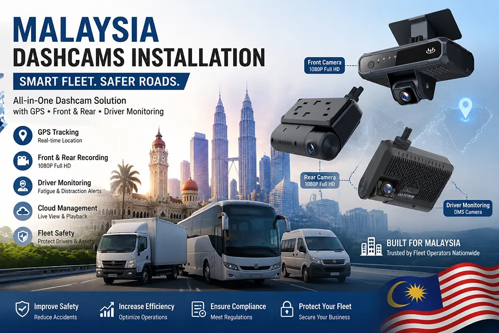
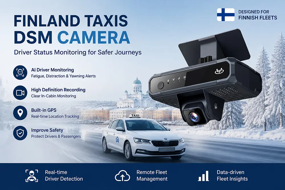
For more information on related products, please refer to "ADAS Cameras" by China YUWEI, an ADAS camera system manufacturer.
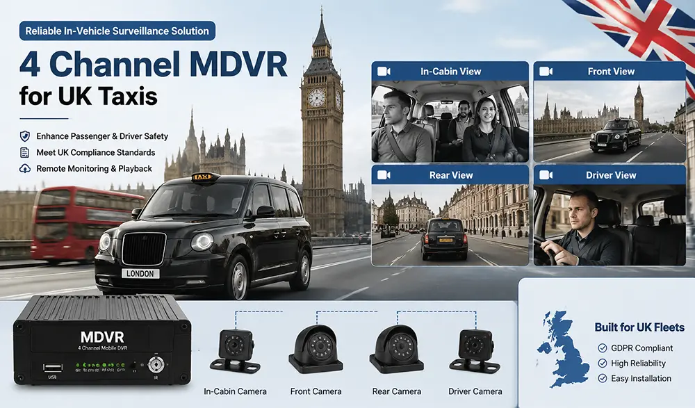
More:1080p Full HD Dash Cam | 4 Channel Mobile DVR | Delivery Fleet Dash Cam