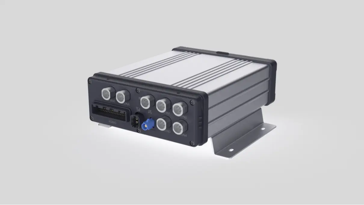


6-Channel Mobile DVR with AI
6-Channel Mobile DVR
The 6-Channel Mobile DVR with AI, developed and manufactured by China's YUWEI, integrates advanced driver assistance systems such as ADAS, DSM, and BSD. It supports 4G broadband multimedia wireless transmission, Wi-Fi communication, and up to 6-channel HD video monitoring and recording. Additionally, it features BDS/GPS dual-mode positioning, RTK high-precision positioning, and inertial navigation capabilities.

Industry Applications:
Widely applicable for use in special vehicles and transport equipment such as forklifts, construction machinery, and ships.
MDVR Features
Advanced Driver Assistance System (ADAS) & Driver Monitoring System (DMS):
AI-powered alerts enhance fleet safety. Video recordings and event reports help fleet managers analyze driving behavior and improve overall performance.
Blind Spot Detection (BSD):
On-screen alerts and audio warnings help prevent collisions and reduce driver stress.
High-Capacity Storage:
Maximum configuration: 2TB HDD/SSD and 512GB SD card. Supports up to 50 days of continuous recording with 6 cameras operating simultaneously.
Vehicle Tracking:
Equipped with a high-performance processor and Linux OS, enabling simultaneous operation of vehicle tracking and video recording modes.
MDVR Specifications
Product Specification
项目 | 详细规格 | 备注 |
Appearance structure | Size: 158.5*144.5*44mm Shell material: die-casting aluminium | |
Protection class | IP67 | |
Environmental suitability | Working temperature: -30℃~70 Storage temperature:-40℃~85℃ | |
Operating Voltage | Operating voltage range: 9 - 32V | |
Support car battery protection: 8.5V±0.5V/12V system, 17V±0.5V/24V system | ||
Ultra-low power consumption | Quiescent current <2mA | |
Support zero power sleep | ||
Ignition wake-up, RTC timer wake-up |
design | ||
Power consumption | Average power consumption less than 24W | |
Super capacitor |
3 super capacitors can supply power to the system | 2~3s working time, save the complete video before power failure |
Indicator light | 2 (1 communication signal, 1 terminal operation indication) | |
Interface | Positioning antenna connector: Fakra-C blue colour | |
Communication antenna connector: Fakra-D | ||
Video | Maximum 6 channels of AHD/CVBS video inputs Power can be supplied to the camera, the output voltage value is 12V, single maximum output current 0.5A | |
1 channel CVBS video output | ||
Audio | 2-way camera recording as standard | |
2W hands-free speaker output | ||
1 SD card | Maximum capacity support 2TB | |
Data Interface | 2 RS232 interfaces, 5V power supply @500mA | |
1 channel 485 interface | ||
Positioning modules | GPS and BeiDou positioning module | |
Communication Module | 4G module | |
SIM card | Drawer pluggable SIM card | |
IO functions | 7 inputs: ACC, left steering, right steering, high beam, low beam, reverse, brake | |
1 open-drain output |
Intelligent video terminal structure function
Structural schematic
hnweb_
Figure 1 Schematic diagram of terminal structure
Front panel diagram of the terminal

Figure 2 Terminal front panel
No. | Name | Function | Description |
1 |
/ |
Communication Indicator | Communication Indicator - Green 1、Flashing once in 5 seconds indicates that there is no signal. 2、Two flashes in 5 seconds means there is signal but not connected to the central server online. |
3、Three flashes in 5 seconds means there is signal and connected to the central server. 4、Power on 10 seconds after the rapid flashing, flashing four times means that the card is not detected, you need to re-unplug the card insertion card | |||
2 |
/ | Operation indicator | Operation Indicator - Red 1、Out indicates normal operation 2、Flashing once a second indicates that the terminal is abnormal. |
3 |
| Switch lock direction |
Rotate clockwise for on, rotate against time for off |
4 | / | SD card and SIM card | Drawer plug-in SIM card slot and plug-in SD card slot |
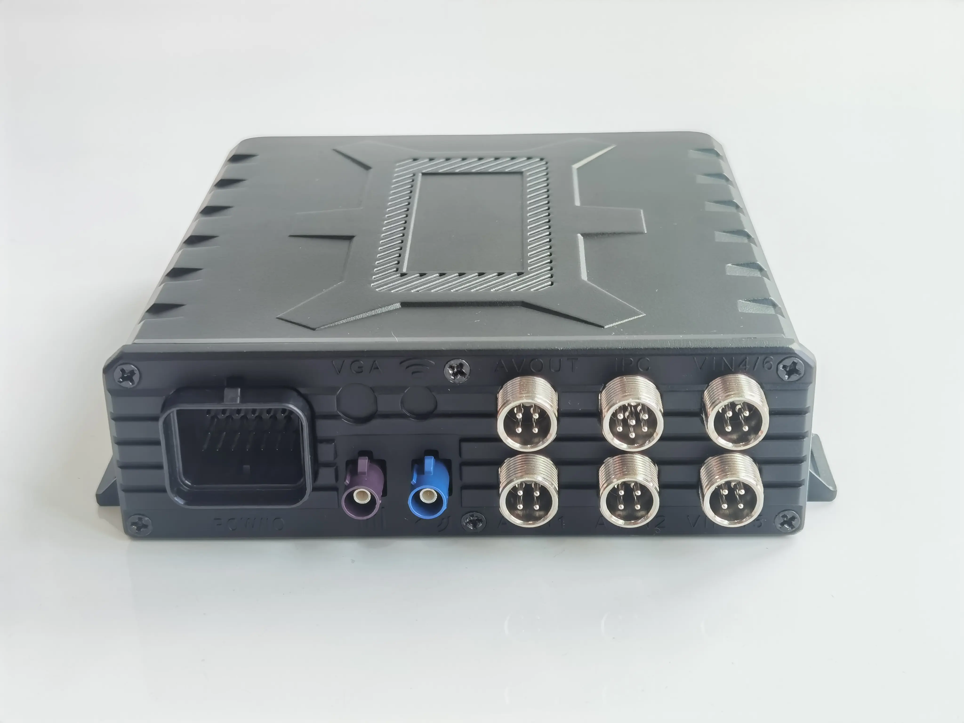
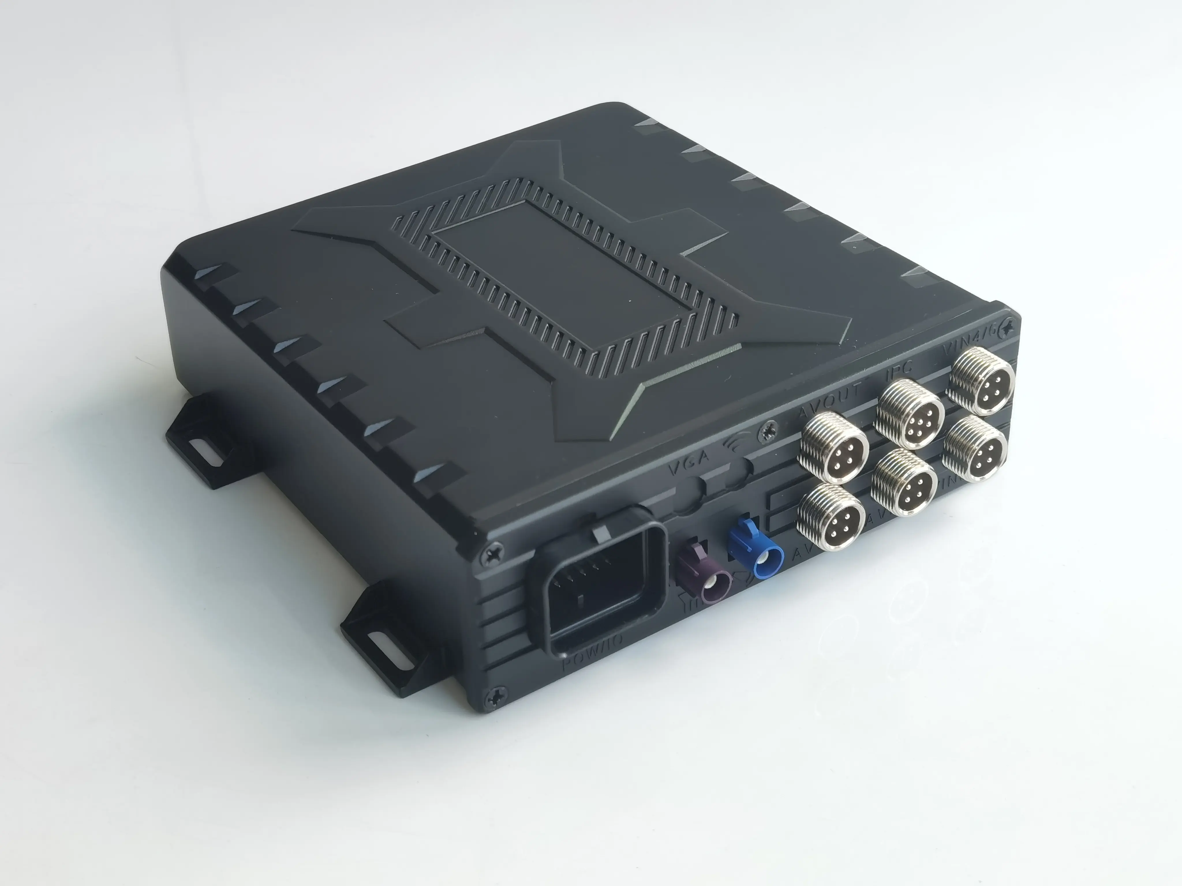
Schematic diagram of the rear panel of the terminal
hnweb_
Figure 3 Rear panel of the terminal
No. | Interface | Interface Name | Function Description |
1 | POW/IO | Main Signal Interface | Power supply, acquisition of vehicle signals |
2 |
| Communication Antenna Interface | Acquisition of base station signals |
3 |
| Positioning Antenna Interface | Acquisition of satellite signals |
4 | AVIN1 AVIN2 | Camera Interface | Supports audio and video inputs (can be connected to DSM and ADAS) |
5 | VIN3/VIN5 VIN4/VIN6 | Camera Interface | Support video input |
6 | IPC | IPC Interface | |
7 | AVOUT | Video Output Interface | Supports video output |


Terminal rear panel main signal interface definition

Figure 4 Main Signal Interface Definition
No. | Signal name | No. | Signal name | No. | Signal name |
1 | Open Leak Signal Output | 10 | Power Ground | 19 | Power Ground |
2 | Ground | 11 | Left steering | 20 | 5V Output |
3 | Right turn | 12 | CAN1L | 21 | EX2_TXD232 |
4 | High beam | 13 | CAN1H | 22 | EX2_RXD232 |
5 | Reverse | 14 | RS485_A | 23 | EX1_TXD232 |
6 | Brake | 15 | RS485_B | 24 | EX1_RXD232 |
7 | Power Ground | 16 | Power Ground | 25 | ACC |
8 | Speed Pulse Input | 17 | Horn Negative | 26 | Power Positive |
9 | Low beam | 18 | Horn Positive |
Terminal rear panel antenna interface

Figure 5 Antenna Interface Schematic
No. | Name | Model |
1 | Communication Antenna | Purple FAKRA D Male |
2 | Positioning Antenna | Blue FAKRA C male |
Terminal rear panel camera interface definition

Figure 6 Input Camera Interface Schematic
Input camera connector model: M12-4P, harness end connector model: aviation head/M12 four holes.
PIN | Function |
1 | 12V power supply |
2 | Ground |
3 | AIN (AVIN1, AVIN2 with audio input; VIN3/5, VIN4/6 this pin is NC) |
4 | VIN |
Terminal rear panel video output interface definition

Figure 7 Video Output Interface Schematic
Input camera connector model: M12-4P, harness end connector model: aviation head/M12 four holes.
PIN | Function |
1 | 12V power supply |
2 | Ground |
3 | NC |
4 | VOUT |
Terminal rear panel IPC interface definition
hnweb_
Fig. 7 Schematic diagram of IPC output interface
IPC interface connector model: M12-6P, harness end connector model: aviation header/M12 six holes.
PIN | Function |
1 | 12V power supply |
2 | Ground |
3 | TXOP |
4 | TXON |
5 | RXIP |
6 | RXIN |
Terminal Wiring Diagram
hnweb_
Active Safety Camera Parameters
ADAS Camera(Y6)
Models | ADAS-A1080PS(Y6) |
Vision Sensor | GC1054 |
Effective Pixel | 1280×720 |
Horizontal FOV | Horizontal 52° |
Depth of Field | 200cm ~ ∞ |
Transmission Method | AHD |
hnweb_
DSM Camera(Waterproof)

Image Sensor | S6 1/2.7" CMOS |
ISP | FH85550M |
Pixel size | 3.0um×3.0um |
Lens | 4G |
Field of view | D=65°H=56°V=31° |
Focal length | 6mm |
Depth of field | 200cm ~ ∞ |
Effective pixels | 1280(H)x720(V) 2 million |
Video Output | AHD 720p |
Frame Rate | 25fps |
System Format | Default PAL (black and white image) |
Wide Dynamic | 85dB |
Signal-to-noise ratio | ≥52dB |
IR Distance | 0~1.2M |
Audio | 无 |
Operating Temperature | -20℃ ~ 70℃ |
Storage Temperature | -30℃ ~ 80℃ |
Operating Humidity | Relative humidity below 90 % |
Power Supply - Current | DC12V ,140mA |
Power Consumption | 1.68W or so |
Cable length | Tail line 250cm±10cm |
Product Configuration List
List of standard equipment
No. | Name | Quantity/set |
1 | Host | 1 |
2 | Positioning Antenna | 1 |
3 | Communication Antenna | 1 |
4 | Mounting cable (power cable) | 1 |
5 | Mounting Stand | 1 |
6 | Lock Key | 1 |
7 | Instruction manual / Certificate of Conformity / Warranty card | 1 |
Option List
No. | Name | Quantity/set |
1 | SD card | 1 |
2 | ADAS | 1 |
3 | DSM | 1 |
Layout requirements
ADAS Camera Arrangement Requirements
Calibration required.
DMS Camera Arrangement Requirements

On the dashboard in front of the steering wheel, the preferred mounting position should be in a straight line with the centre line of the steering wheel, as indicated by the centre line in the figure below. If it is inconvenient to install the centre point or affects the driver's driving vision, it can be moved to the left and right sides of the steering wheel, with the maximum range of movement not exceeding 25° left and right, and the pitch angle of 5°≤15°≤15° (the marked line in the figure below). As shown in the figure below:
Communication antenna layout requirements
The location should be as close as possible to the car windows and hidden, to ensure the communication signal strength and prevent damage;
The communication antenna should be far away from other sensitive electronic equipment and metal, such as sound system, radio, etc.;
The distance between the antenna and other antennas is not less than 50cm to avoid affecting the signal strength.
Positioning Antenna Arrangement Requirements
The positioning antenna should be orientated with the receiving side upwards and not covered by any debris, with at least a 60° view of the sky and an inclination of no more than 15°.
The recommended mounting position for the positioning antenna is under the front windscreen, on the roof of the vehicle or in the most unobstructed position possible.
The positioning antenna has a suction iron/ or adhesive on the bottom (flat, with text) to attach it to the car for fixing, otherwise it must be fixed with double-sided adhesive.
Spacing from the communication antenna should be no less than 50cm to avoid affecting the signal strength and should be kept away from other sensitive electronic equipment and metal such as sound systems, radios, cameras, etc.
Email:hello@yuweitek.com